Summary
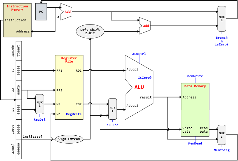
MIPS processor datapath
- Fetch
- retrieve instruction from memory
- index according to program counter(PC) register
- Decode
- find the operation that’s needed
- Operand Fetch
- fetch operands needed, either registers or immediate operand
- Execute
- perform the required operation in the ALU
- Result Write
- store the result of the operation back into a register, if necessary
Supported instructions
add,sub,and,oraddilw,swbeqslt
limited set of instructions supported by this simplified implementation,
andiandorido not work due to the sign extension on the immediate value
Concept
PC register
- incremented by 4 at every rising clock edge
clock helps to synchronise things, so that we only read PC after its been incremented
Multiplexers
- output one of multiple inputs
- control signal: selects which input to use
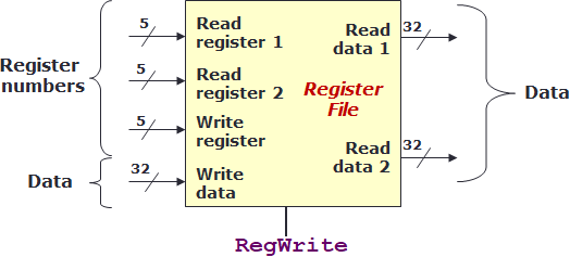
Register file
- collection of the registers
- control signal: 1 bit, determines whether to write to an output register
- inputs
- RR1, read register 1 -> first register to read from
- RR2, read register 2 -> second register to read from
- WR, write register -> which register to write to
- WD, write data -> data to be written
- outputs
- RD1, read data 1 -> value at the first register
- RD2, read data 2 -> value at the second register
ALU
- arithmetic logic unit, for logical and arithmetic ops
- inputs
- 2 32-bit numbers
- outputs
- result of operation
- 1 bit
is0indicator
- control signal: 4 bits to select the operation to perform
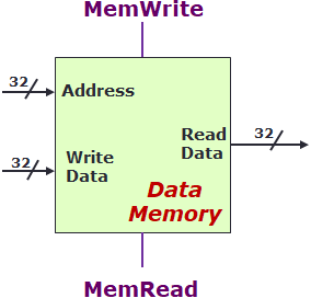
Data memory
- data storage, RAM
- load/write data
- inputs
- address -> memory address to read from/write to
- WD, write data -> data to be written
- outputs
- RD, read data -> data that was read
- RD, read data -> data that was read
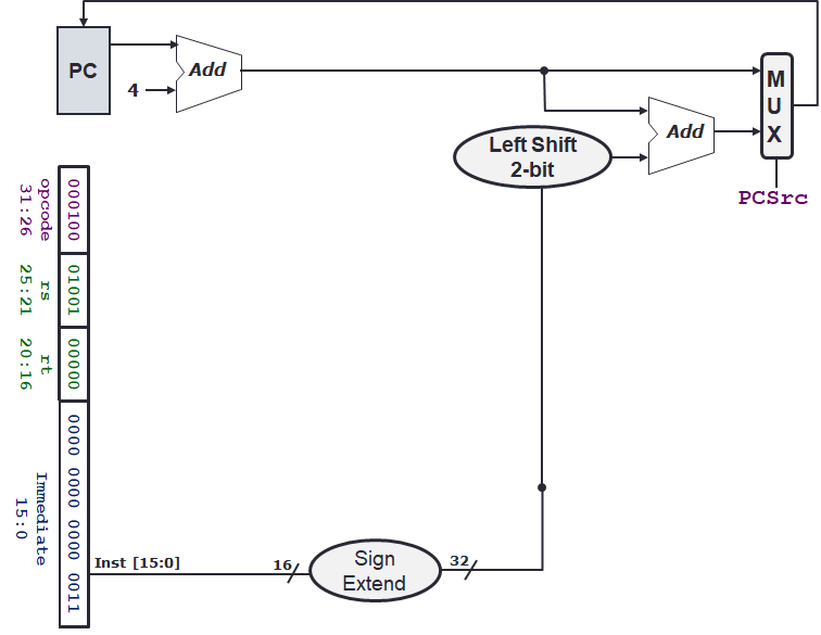
Branching
- immediate operand is used to increment the PC register
- if branch not taken:
PC = PC + 4as normal - if branch is taken:
PC = PC + 4 + (imm << 2)
Application
Datapath of some instructions
| Instruction | RR1 | RR2 | WR | WD(Register File) | Op1 | Op2 | Address | WD(Data Memory) |
|---|---|---|---|---|---|---|---|---|
lw $24, 0($15) | $15 | $24 | $24 | Mem([$15] + 0) | [$15] | 0 | [$15] + 0 | [$24] |
beq $1, $3, 12 | $1 | $3 | $3 | [$1] - [$3] or Mem([$1] - [$3]) | [$1] | [$3] | [$1] - [$3] | [$3] |
sub $25, $20, $5 | $20 | $5 | $25 | [$20] - [$5] | [$20] | [$5] | [$20] - [$5] | [$5] |
beqchecks that the differnece between the operands are 0, in order to branch
Extra
Circuitikz diagrams
use circuitikz designer for a gui circuit builder