sequential circuits
Summary
Characteristic tables
- SR flip-flop
| Action | |||
|---|---|---|---|
| 0 | 0 | No change | |
| 0 | 1 | 0 | Reset |
| 1 | 0 | 1 | Set |
| 1 | 1 | Invalid |
- D flip-flop
| Action | ||
|---|---|---|
| 0 | 0 | Reset |
| 1 | 1 | Set |
- JK flip-flop
| Action | |||
|---|---|---|---|
| 0 | 0 | No change | |
| 0 | 1 | 0 | Reset |
| 1 | 0 | 1 | Set |
| 1 | 1 | Toggle |
- T flip-flop
| Action | ||
|---|---|---|
| 0 | No change | |
| 1 | Toggle |
Excitation tables
- SR flip-flop
| 0 | 0 | 0 | X |
| 0 | 1 | 1 | 0 |
| 1 | 0 | 0 | 1 |
| 1 | 1 | X | 0 |
- D flip-flop
| 0 | 0 | 0 |
| 0 | 1 | 1 |
| 1 | 0 | 0 |
| 1 | 1 | 1 |
- JK flip-flop
| 0 | 0 | 0 | X |
| 0 | 1 | 1 | X |
| 1 | 0 | X | 1 |
| 1 | 1 | X | 0 |
- T flip-flop
| 0 | 0 | 0 |
| 0 | 1 | 1 |
| 1 | 0 | 1 |
| 1 | 1 | 0 |
Sinks
- once the circuit enters this state
- it never moves out
Self-correcting
- if the circuit enters any unused (invalid) state
- it is able to transit to a valid state after a finite number of transitions
Concept
Types of sequential circuits
- synchronous: outputs change at a specific time
- asynchronous: outputs can change at any time
Stable states
- bistable - 2 stable states
- monostable - 1 stable state
- astable - no stable states
Bistable logic devices
- latches -> pulse-triggered
- flip-flops -> edge-triggered, rising or falling edge
flip-flops are just latches but triggered slightly differently
SR latch
- set and reset
- store current state otherwise
- has an invalid condition
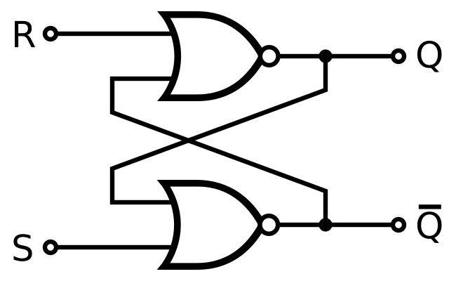
an active-low SR latch would have the NOR gates replaced with NAND
| Action | |||
|---|---|---|---|
| 0 | 0 | No change | |
| 0 | 1 | 0 | Reset |
| 1 | 0 | 1 | Set |
| 1 | 1 | Invalid |
the characteristic table shows the next state, based on the inputs and current state
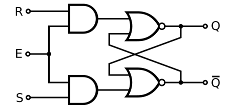
Gated SR latch
- SR latch with enable pin
- only changes if the enable pin is high
Gated D latch
- change to
- removes the impossible condition
| Action | |||
|---|---|---|---|
| 1 | 0 | 0 | Reset |
| 1 | 1 | 1 | Set |
| 0 | X | No change |
JK flip-flop
- uses the impossible condition as a toggle
| Action | ||||
|---|---|---|---|---|
| 0 | 0 | ↑ | No change | |
| 0 | 1 | ↑ | 0 | Reset |
| 1 | 0 | ↑ | 1 | Set |
| 1 | 1 | ↑ | Toggle |
T flip-flop
- JK flip-flop without individual set and reset pins
| Action | |||
|---|---|---|---|
| 0 | ↑ | No change | |
| 1 | ↑ | Toggle |
Asynchronous inputs
- PRE and CLR to immediately set and reset
Application
State diagram
a 4 state circuit requires 2 flip-flops, for extra unused states, fill with don’t care terms
Circuit analysis
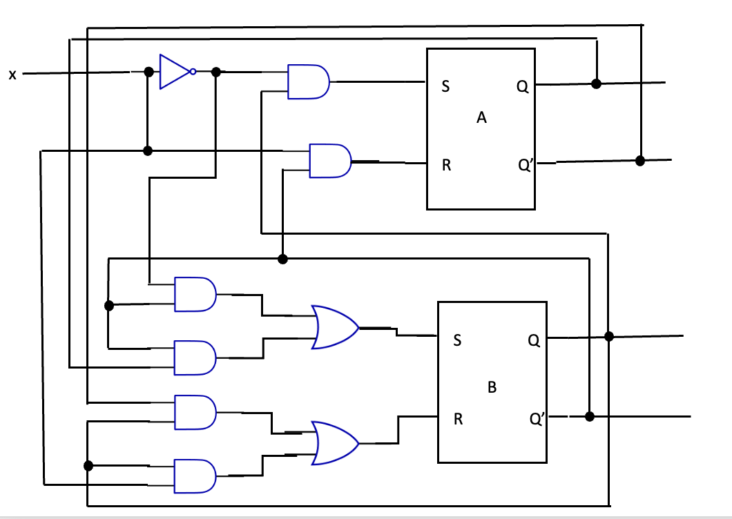
Constructing a sequential circuit
Extra
Tikz template for state diagrams
latex
\usepackage{tikz}
\usetikzlibrary{calc}
% https://tex.stackexchange.com/questions/354199/how-to-make-an-arrow-from-a-node-to-itself-have-a-nice-arc
\def\loopsize{6mm}
\newcommand\round[5][-]%
{
  \draw[#1]
    ($ (#2.#3) + {cos(#3)}*(0,{0.71*(\loopsize/2)}) - {sin(#3)}*({0.71*(\loopsize/2)},0) $)
    arc (180+#3-45:180+#3-45-270:\loopsize/2)
    node[midway, #4] {#5};
}
\tikzstyle{vertex}=[draw,circle,minimum size=18pt,inner sep=0pt,node distance=4cm]
\begin{document}
\begin{tikzpicture}[auto,thick]

  \node[vertex] (a) {00};
  \node[vertex,right of=a] (b) {01};
  \node[vertex,below of=a] (c) {10};
  \node[vertex,right of=c] (d) {11};

  \round[->]{a}{135}{}{0/0};
  \draw[->, bend left=15] (a) to node[midway] {1/0} (b);

  \draw[->, bend left=15] (b) to node[midway] {0/1} (a);
  \draw[->, bend left=15] (b) to node[midway] {1/0} (d);

  \draw[->, bend left=15] (c) to node[midway] {0/1} (a);
  \round[->]{c}{-135}{}{1/0};

  \draw[->, bend left=15] (d) to node[midway] {0/1} (a);
  \draw[->, bend left=15] (d) to node[midway] {1/0} (c);
\end{tikzpicture}
\end{document}