mips pipelining
Summary
Pipelined datapath
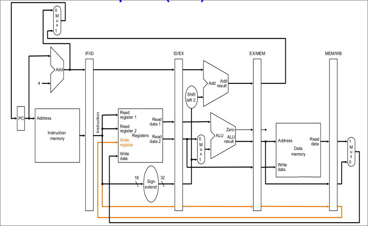
Pipeline registers
- IF/ID
- instruction(32-bit)
PC + 4
- ID/EX
- values read from registers
- 32-bit immediate(after sign extension)
PC + 4- WR
- EX/MEM
PC + 4or(PC + 4) + (imm × 4)- ALU result
- isZero
- RD2(used for
lwandsw) - WR
- MEM/WB
Pipeline control path
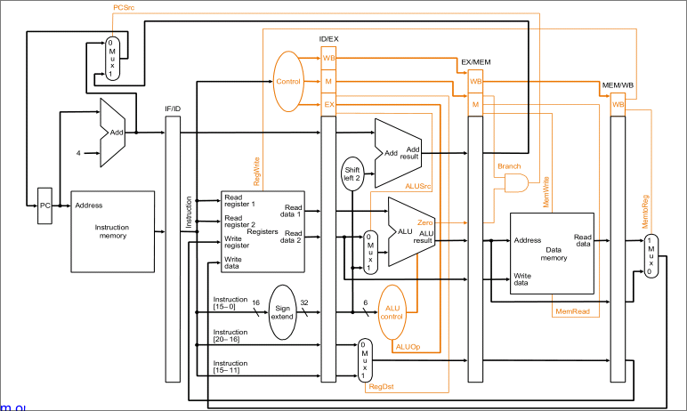
Concept
Instruction pipelining
- keep every part of processor busy at all time
- different processor units are working in parallel
- sequential execution - execute each instruction one after the other
- pipelined execution - start the next instruction once the first stage of the previous is done
Perfect pipelining
- each subsequent instruction is only delayed by one clock cycle
Extra
Tikz template for drawing pipeline tables
latex
\usepackage{tikz}
\usetikzlibrary{arrows.meta,positioning,calc}
\tikzset{
  stage/.style={
    draw, thick, minimum size=0.8cm, align=center
  },
  stall/.style={stage,fill=gray!30},
  flush/.style={stage,fill=red!25},
  nop/.style={draw=none,fill=white!0},
  IF/.style={stage,label=center:{IF}},
  ID/.style={stage,label=center:{ID}},
  EX/.style={stage,label=center:{EX}},
  MEM/.style={stage,label={[font=\tiny]center:{MEM}}},
  WB/.style={stage,label=center:{WB}},
}

% \pipeline{inst}{cycle}{stage list}
\newcommand{\pipeline}[3]{%
  \foreach [count=\i] \stage in {#3} {
    \node[\stage] at($(#2+\i-1,-#1)$) {};
  }
}

\begin{document}
\begin{tikzpicture}[thick]
% cols: instructions
\foreach \i in {1,...,3} {
	\node[align=right] at(0,-\i) {\i};
}
% rows: cycles
\foreach \i in {1,...,16} {
		\node at(\i,0) {\i};
}

\pipeline{1}{1}{IF,ID,EX,MEM,WB}
\pipeline{2}{6}{IF,ID,EX,MEM,WB}
\pipeline{3}{11}{IF,ID,EX,MEM,WB}

\end{tikzpicture}
\end{document}